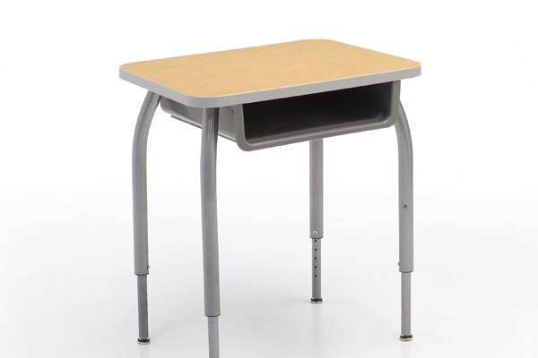
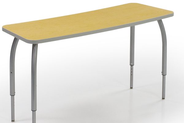
ShuttleZone Student Desks
ShuttleZone tables are specially designed to meet the needs and opportunities of today’s changing schools.
Mobile, technology-friendly desks and storage units that instantly connect with the patented pushbutton ShuttleLatch. Use pieces alone or combine shapes.
• Premium hardware
• 14-gauge steel legs
• Metal-to-metal bolted connections throughout
• PVC banded work-surfaces
• Steel-reinforced high density particle board
• Vertical and horizontal bumper protection
• Rugged PVC edging
• Premium, heavy-duty hardware throughout
[popup_trigger id=”2174″ tag=”span”]View Specs[/popup_trigger]
ShuttleZone tables are specially designed to meet the needs and opportunities of today’s changing schools.
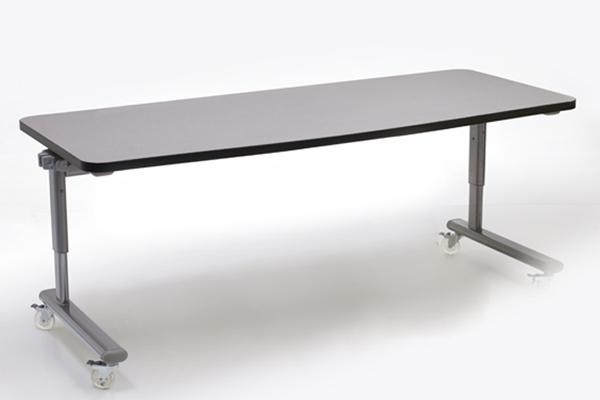
With their streamlined design, ShuttleZone Computer Tables make ideal laptop tables, but they’re also rugged enough for your heaviest equipment.
ShuttleZone tables are specially designed to meet the needs and opportunities of today’s changing schools.
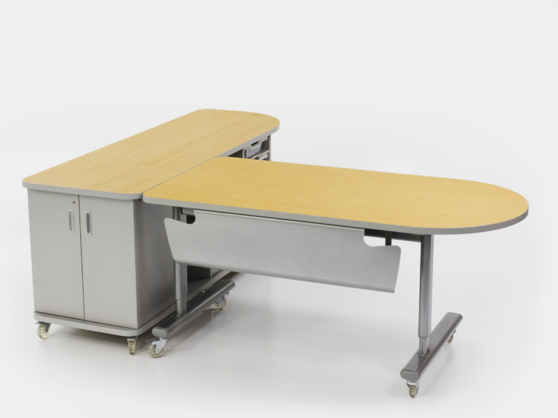
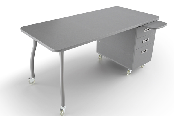
Techera is the perfect instructor desk for technology-intensive learning environments like computer labs and media centers.
Techera is the perfect instructor desk for technology-intensive learning environments like computer labs and media centers.
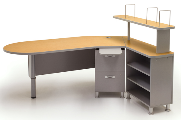
The ShuttleZone Open Space Collection separates the traditional workspace into more manageable, technology-friendly pieces to suit today’s more fluid classrooms.
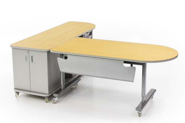
Mobile, technology-friendly desks and storage units that instantly connect with the patented pushbutton ShuttleLatch.
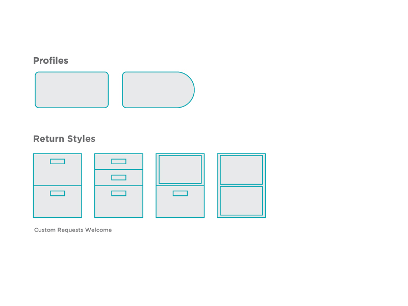
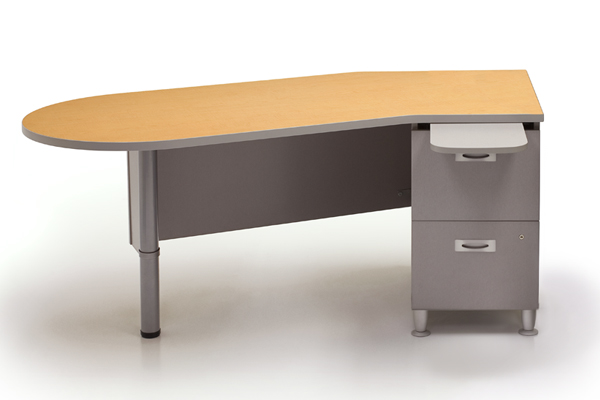
ShuttleZone Pedestal Desks are the choice of educational professionals who need a quality, technology friendly workspace at a reasonable price.
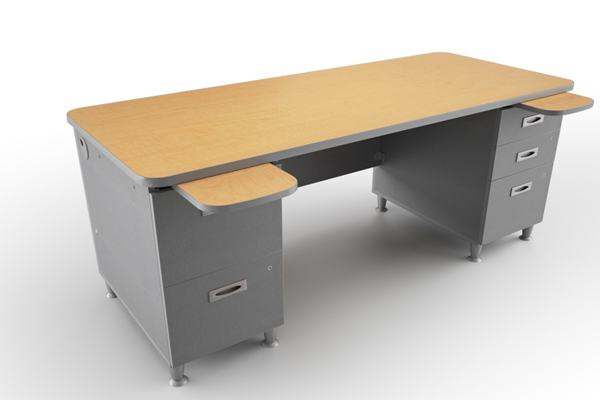
ShuttleZone Pedestal Desks are the choice of educational professionals who need a quality, technology friendly workspace at a reasonable price.
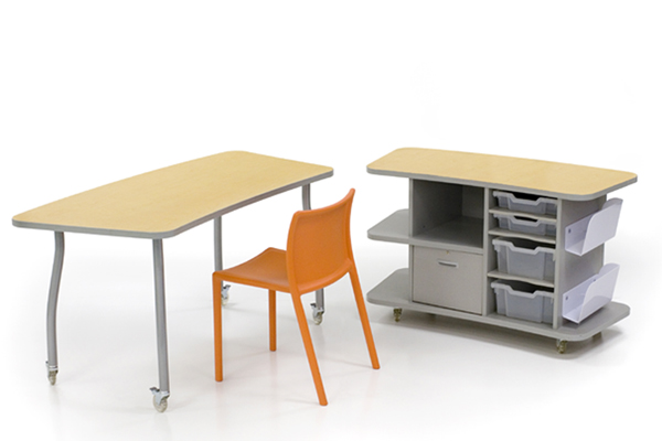
Super-tough and transportable, ShuttleZone Mobile Cabinets offer a smarter, more flexible solution for managing supplies and classroom equipment allowing storage to move easily within a room or to relocate from room to room as your needs change.
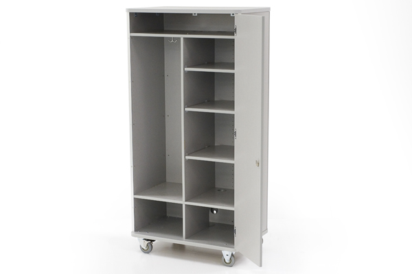
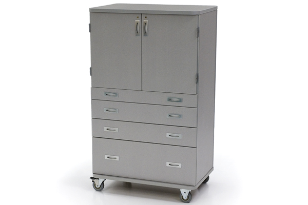
Super-tough and transportable, ShuttleZone Mobile Wardrobes provide a smarter, more flexible solution for managing supplies, classroom equipment and teachers’ personal belongings.
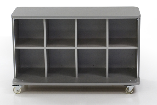
Super-tough and transportable, ShuttleZone Mobile Cabinets offer a smarter, more flexible solution for managing supplies and classroom equipment.
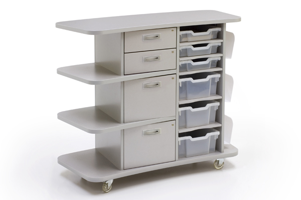
ShuttleZone Satellite Support Modules transport supplies and materials wherever you need them. Choose from two heights; the desk height works great with our ShuttleZone Desks while the standing height doubles as a lectern.
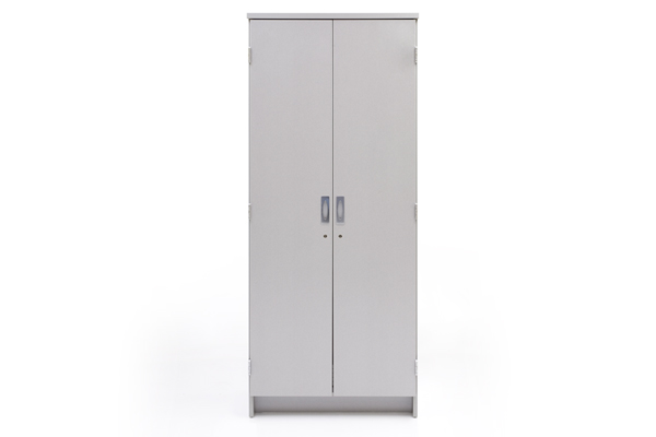
Super-tough ShuttleZoneStationary Cabinets offer a smarter, more flexible solution for managing supplies and classroom equipment.