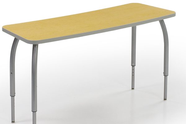
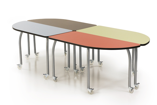
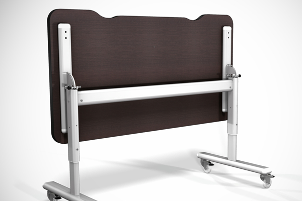
The Single Pedestal desk shall be specifically designed to withstand the structural stress of frequent movement and reconfiguration and shall also be designed to seamlessly accommodate a number of add-on options – including power/data modules, center drawers, and modesty panel or wire manager. There shall be an assembled pedestal mounted underneath the worksurface on either the left or right side. The Single Pedestal desk shall be designed to be combined with the system’s other interchangeable shapes and sizes for flexible configurations.
Overall Dimensions
- 30″ Deep
- 54″, 60″ or 72″ Wide
- 29″ High
Worksurface – The worksurface of the teacher conference desk shall be constructed of 1 1-8”” thick, high-density particleboard with HPL laminate on the top and a standard backer on the underside. The edging shall be 2mm contour banded PVC. There shall be 5/16-18x22mm metal inserts in the underside of the work surface that shall be used to anchor each leg. For arc and S legs, there shall be a total of five inserts for each leg, spaced and located to maximize anchoring strength and structural support – with the 2 inserts closest to the corner edge of the table being paired and located in such a way that the table and legs can withstand more than 250 lbs of diagonal impact force. For pedestal legs, there shall be two inserts per leg with additional leg support provided by a 30mm x 70mm x 14 ga tubular steel horizontal support/worksurface support bar that shall be anchored to each leg and to the underside of the worksurface. For all tables over 54″ wide that are equipped with either of the arc legs or the S leg there shall be a 48” long, 1” x 1” x 3” x 1” x 1″, 14 gauge, powder coated hat channel brace that shall be securely anchored to the underside of the worksurface in 12 locations to prevent the worksurface from sagging.
Pedestal – The pedestal shall mount under the worksurface on either the left or right side using 5/16-18 joint connector bolts into 5/16-18 inserts embedded into the bottom side of the worksurface. The pedestal will be constructed of ¾” high-density particleboard, laminated 2 sides with low pressure laminate. The edging shall be 2mm PVC. 1/4-20 joint connector bolts and 1/4-20 steel cross dowels will be used to construct the pedestal panel parts. The pedestal will have the options to include large file drawers or small pencil drawers. Other options will be open shelves and a door on the opposite side of the drawers. Pedestal would include adjustable aluminum feet or 3” locking casters, mounted in a through-bolt fashion to the base of the cabinet.
Each pedestal unit shall contain a concealed, entrapped auxiliary writing surface. This surface shall be constructed of ¾” particle board with low pressure laminate 2 sides and full perimeter edgeband of 2mm PVC. For the sake of safety, the shape of the protruding edge shall be of an elliptical shape. Construction of the pedestal shall be such that this writing surface shall extend beyond the work surface 12” in the open position, but no further. In the closed position, the auxiliary writing surface shall not extend past the work surface, but shall extend past the pedestal by 1” so that the finger groove in the bottom can be accessed and the writing surface can be deployed
Drawers – Drawer front is to be constructed with ¾ a high-density particleboard laminated 2 sides with low pressure laminate. The edging shall be 2mm PVC. Drawer front shall include recessed brushed steel pulls and optional locks. Construction of the drawer box shall consist of a ¼” particleboard bottom with white melamine applied on both sides. Also ¾” particleboard back panel with white melamine applied on both sides. The sides of the drawer shall be constructed of 16ga powder coated steel drawer slides. All components are attached using coarse wood screws.
Wire Access: On each side of the pedestal shall be located one 2 ½” diameter round holes into which are inserted grommets with covers for cords and wires: each shall be positioned 2 ½” from the back edge and 1 1/2” from the top. Another grommet shall be positioned on the back of the pedestal and shall be positioned 6” from the back edge and 2” from the bottom.
Legs – The teacher conference desk shall be designed to use either: 1) the S-Leg; 2) the Fixed Arc leg; or, 3) the Pedestal Leg.
1) S Leg – The S leg shall be constructed of 1 1/2″, 14 gauge, powder-coated, steel tubing, bent in two radii. Each leg shall rest on a non-adjustable, stainless steel glide or shall be equipped with one optional 3″, 100 lb locking caster. Each leg section shall be full 360 degree perimeter tungsten arc welded to an extra thick, extra-strength, 6″ x 6″ x 3/16″ steel anchoring plate.
There shall be 5 attachment holes in each plate, each specifically spaced to prevent the leg from being installed in the wrong orientation. Each attachment hole shall accommodate a 5/16 x 18 x 5/8 machine bolt that shall anchor into a 1/4 x 20 x .78″ deep threaded metal insert which shall be permanently imbedded at each corner of the worksurface to provide maximum resistance to breakout under abusive impact conditions.
2) Fixed Height Arc Leg – The Fixed Arc leg shall be constructed of 1 1/2″, 14 gauge, powder-coated, steel tubing, formed at the top section into an arc with a radius of 23″. Each leg shall rest on either a non-adjustable, stainless steel glide (3 per table), or an adjustable, stainless steel glide (1 per table) which shall be used to level the table on uneven floors. Additionally, there shall be four optional 3″, 100 lb locking caster available in place of the glides. Each leg section shall be full 360 degree perimeter tungsten arc welded to an extra thick, extra-strength, 6″ x 6″ x 3/16″ steel anchoring plate. There shall be 5 attachment holes in each plate, each specifically spaced to prevent the leg from being installed in the wrong orientation. Each attachment hole shall accommodate a 5/16 x 18 x 5/8 machine bolt that shall anchor into a 5/16-18x22mm deep threaded metal insert which shall be permanently imbedded at each corner of the work surface to provide maximum resistance to breakout under abusive impact conditions.
3) Pedestal Leg – Each adjustable height pedestal leg shall consist of an Upper Leg section, a Lower Leg section and a plastic separating bushing. The Upper Leg section shall be constructed of a powder coated assembly of two 14 gage electric welded oval steel tubes – a horizontal top support tube and an outer vertical column. The horizontal top support section shall measure 30mm x 70mm and the outer vertical column shall measure 40mm x 80mm. The Upper Leg section shall incorporate an extra strength, hidden tubular interlock design located at the point where the upper horizontal top support and outer vertical column are joined. This hidden interlock results from the upper end of the outer vertical column passing through an identically matched oval cutout in the underside of the upper horizontal top support, such that the outer vertical column rests tightly against the upper inside tube surface of the upper horizontal top support. The outer vertical column shall then be metal inert gas (MIG) arc welded to the upper horizontal top support by means of a continuous 360 degree weld around the full perimeter of the 40mm x 80mm outer vertical column. The horizontal top support tube shall have two attachment holes drilled through for the purpose of attaching the work surface. Each attachment hole shall accommodate a 5/16-18 machine bolt that shall anchor into a 5/16-18x22mm deep threaded metal insert which shall be permanently imbedded in the underside of the work surface to provide maximum resistance to breakout under abusive impact conditions. The outer vertical column shall be drilled in two locations to accommodate a ¼-20 height adjustment anchor screw.
The Lower Leg section shall be constructed of a powder coated assembly of two 14 gage electric welded oval steel tubes – a lower horizontal floor runner and an inner vertical column. The lower horizontal floor runner shall measure 40mm x 80mm and the inner vertical column shall measure 30mm x 70mm. The Lower Leg section shall incorporate an extra strength, hidden tubular interlock design located at the point where the lower horizontal floor runner and inner vertical column are joined. This hidden interlock results from the lower end of the inner vertical column passing through an identically matched oval cutout in the top of the lower horizontal floor runner, such that the inner vertical column rests tightly against the lower inside tube surface of the lower horizontal floor runner. The inner vertical column shall then be metal inert gas (MIG) arc welded to the lower horizontal floor runner by means of a continuous 360 degree weld around the full perimeter of the 30mm x 70mm inner vertical column. The lower horizontal floor runner shall be drilled and tapped at 6 different 1” increments and shall rest on two non-adjustable, stainless steel glide or two optional 3”, 100 lb capacity, double-locking casters.
Both ends of the horizontal top support tube and the lower horizontal floor runner shall be fitted with large, soft-edged, ABS plastic end caps that are sleeve-ribbed to ensure a snug fit. Each end cap shall also include a hidden anchor system to protect against accidental or unauthorized removal. This protection shall be accomplished by means of a latching element molded into the end cap, which, as it is installed, shall enlarge and capture the threaded stem of the glide or caster, or of the work surface anchoring bolt, securing the end cap in place.
Horizontal Support/Worksurface Support Bar: To provide for maximum support for each leg, the right and left pedestal leg shall be anchored to an oval 40mm x 80mm x 14 ga steel tube horizontal support bar that shall span the distance between the two legs. The support bar shall be securely anchored to each leg by means of two 5/16-18 screws. The 5/16-18 screws shall be threaded into metal press nuts on the 11 ga steel brackets that are welded to each leg. This support bar shall also be designed provide additional support to the worksurface and shall be welded to the middle of the support bar and anchored into the underside of the worksurface by means of a 5/16-18 screw into a threaded metal insert in the underside of the worksurface.
Optional Modesty Panel/Wire Manager – The steel Modesty Panel/Wire manager shall measure 40″ long x 11″ high, and shall be made from 16ga powder coated steel. It shall be anchored to the worksurface using 5/16-18x22mm bolts and 5/16-18mm steel inserts and shall be stiffened with 16 gauge powder coated steel straps.